| overload | التاريخ: الأحد, 2012-11-04, 10:40 AM | رسالة # 1 |
|
عضو
مجموعة: المدراء
رسائل: 39
حالة: Offline
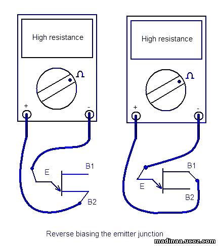
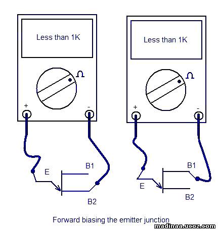
| 1. Measuring the resistance between B1 and B2 terminals. Set your digital multimeter in resistance mode.Connect the positive lead of multimeter to the B1 terminal and negative lead to the B2 terminal.The multimeter will show a high resistance ( around 4 to 10K ). Now connect the positive lead to B2 terminal and negative lead to B1 terminal.Again the multimeter will show a high resistance (around 4 to 10K ).Also both the readings will be almost same. 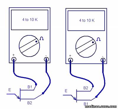 2.Reverse biasing the emitter junction. Set the digital multimeter in resistance mode.Connect negative lead of the multimeter to the emitter and positive lead to the B1.The multimeter will show a high resistance (around 100′s of K’s).Now connect the negative lead once again to the emitter and positive lead to B2.Again the meter will show a high resistance.In both cases the reading will be almost same.This test is almost like reverse biasing a diode. 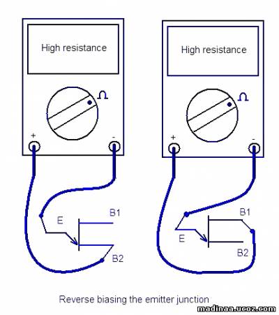 3.Forward biasing the emitter junction. Set the digital multimeter in resistance mode.Connect the positive lead to the emitter and negative lead to B1.The multimeter will show a low resistance (around few 100 ohms).Now connect the positive lead once again to the emitter and ngative lead to the B2 terminal.Again the multimeter will show a low resistance reading (around few 100 ohms).In both cases the reading will be almost same.This test is almost like forward biasing a diode. 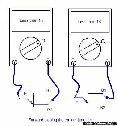
|
| |
|
|